
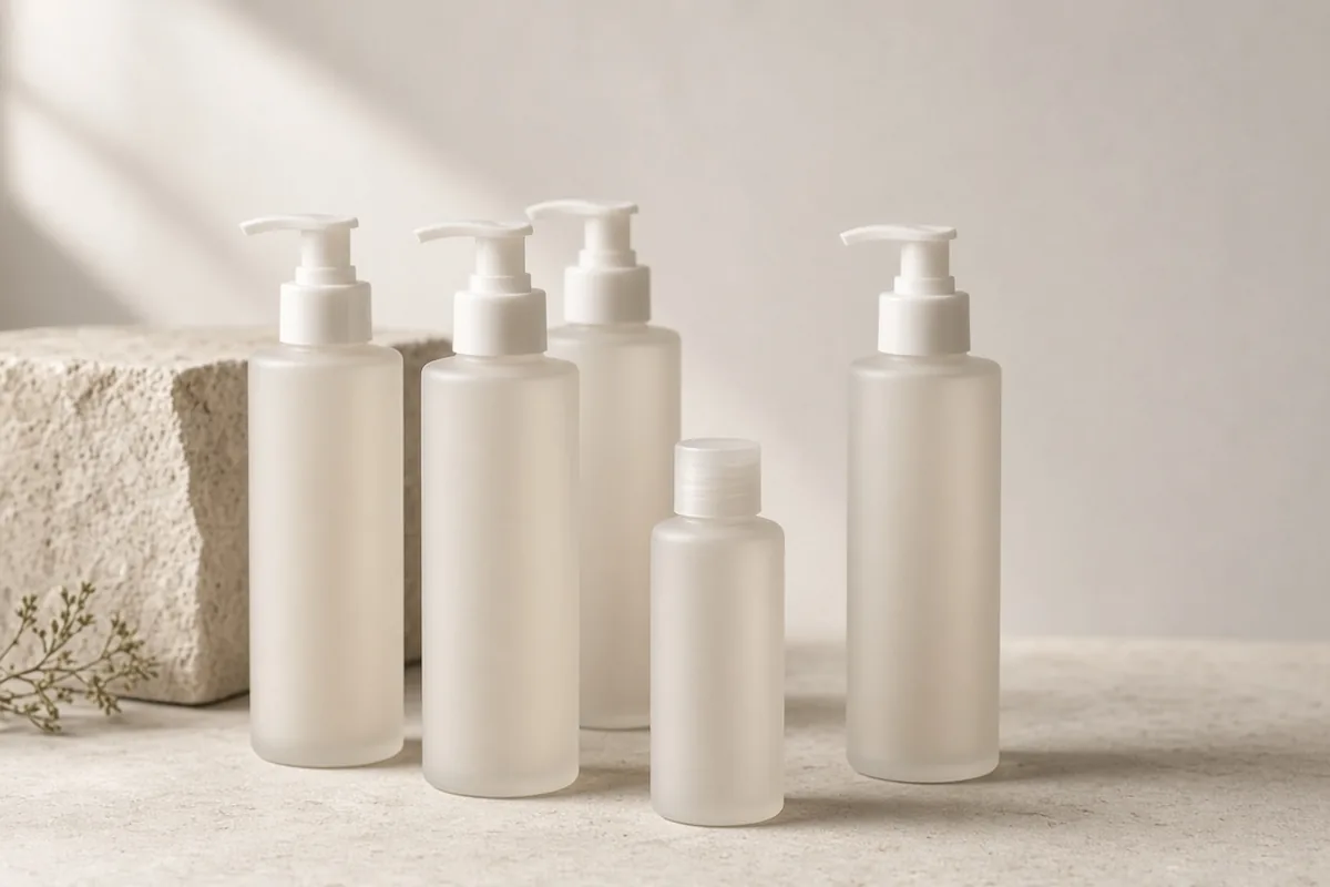
Specifying a lotion pump bottle requires matching four internal mechanical tolerances to the emulsion and container geometry: pairing the Glass Packaging Institute (GPI) neck finish (20/410, 24/410, or 28/410) with 11 to 18 in-lbs of ASTM D3198 application torque, sizing the dosing chamber (0.5 to 4.0 cc per stroke) to formulations below the 45,000 to 50,000 cP atmospheric cavitation ceiling, isolating the SUS 304 or SUS 316H return spring from low-pH or antioxidant actives, and cutting the FBOG (“From Bottom of Gasket”) dip tube to maintain 0.8 to 1.5 mm of floor clearance with a 45° bevel or inverted V-cut intake. Mismatching any of these parameters causes closure thread back-off and leakage during parcel transit, hydraulic actuation forces that exceed the 3.0 lbf (13.3 N) one-hand accessibility limit, metallic discoloration on initial strokes, or pump suction failure that leaves 8% to 15% of the bottle’s net lotion volume wasted at the base.
Where our companion guide on what makes a pump bottle easier to hold and press examines the external human-factors geometry from the Arthritis Foundation Ease of Use Rigid Packaging Guide and ISO 22015:2019 (such as keeping palm depression force below 3.0 pounds, maintaining a 2.5 to 3.0 inch container grip span, and stabilizing the base against tipping), and our foam pump bottle mesh ratio and liquid viscosity guide covers wide-neck (30/410 to 43/400) coaxial dual-piston foamers for water-thin (1 to 50 cP) surfactant solutions, this engineering specification covers the internal components that determine whether a single-chamber emulsion lotion bottle seals, primes, and evacuates cleanly. Whether the container holds a daily body emulsion from the personal care section or a post-workout rinse-out conditioner used alongside the active-day hair care guide, the specification matrix below maps standard bottle capacities to neck finish, stroke output, viscosity, and dip tube geometry.
Container Capacity (mL / fl oz) |
Standard GPI Neck Finish |
Stroke Dosage (cc / mL) |
Target Dynamic Viscosity (cP / mPa*s) |
ASTM D3198 Application Torque (in-lbs / N*m) |
Dip Tube Bore ID & FBOG Clearance |
Primary Personal-Care Applications & Line Equipment |
|---|---|---|---|---|---|---|
50 to 150 mL (1.7 to 5.0 fl oz) |
20/410 or 24/410 (1.5 thread turns) |
0.5 to 1.0 cc (100 to 200 strokes per 100 mL) |
500 to 5,000 cP |
8 to 12 in-lbs (20/410) or 11 to 15 in-lbs (24/410) |
1.8 to 2.5 mm ID; 0.8 to 1.2 mm floor clearance (45° bevel) |
Facial lotions, niacinamide serums, fluid sunscreens; filled on diving-nozzle piston cosmetic filling machine lines |
200 to 350 mL (6.7 to 12.0 fl oz) |
24/410, 24/415, or 28/410 |
1.5 to 2.0 cc (125 to 167 strokes per 250 mL) |
3,000 to 15,000 cP |
11 to 15 in-lbs (24 mm) or 14 to 18 in-lbs (28 mm) |
3.0 to 3.8 mm ID; 1.0 to 1.5 mm floor clearance (45° bevel or V-cut) |
Daily hand and body lotions, leave-in hair conditioners, creamy body washes; <3.0 lbf two-finger or palm press |
500 to 1,000 mL (16.9 to 33.8 fl oz) |
28/410, 28/400, or 38/400 |
3.5 to 4.0 cc (125 to 143 strokes per 500 mL) |
15,000 to 45,000 cP |
14 to 18 in-lbs (28/410) or 17 to 23 in-lbs (38/400) |
4.0 to 5.2 mm ID; 1.0 to 1.5 mm clearance (notched V-cut) |
Rich shea body milks, high-oil barrier lotions, backbar conditioners; wide palm actuator head |
>50,000 cP Ceiling (Non-slumping pastes) |
Airless snap/crimp neck or laminate tube | 0.5 to 1.5 cc airless piston or squeeze orifice |
>45,000 to 50,000 cP (Dip tube cavitates) |
Snap-fit crimp or heat/ultrasonic tube seal | No dip tube (Airless follower plate or bottom-up tube fill) | Heavy anhydrous body butters, zinc barrier pastes; requires airless pack or cosmetic tube filling machine |
GPI and SP-400 Neck Finish Geometry (20/410, 24/410, 28/410) and Application Torque
Every threaded lotion pump bottle manufactured in North America, Europe, and Asia follows the two-number neck finish nomenclature standardized by the Glass Packaging Institute (GPI) and the Voluntary Society of the Plastics Industry (SPI) SP-400 series (alongside European CETIE equivalents). As detailed in CL Smith Packaging’s GPI neck finish dimensional tables, the slash-separated code (Diameter / Thread Style, such as 24/410 or 28/410) defines both the radial thread diameter and the vertical closure skirt engagement.
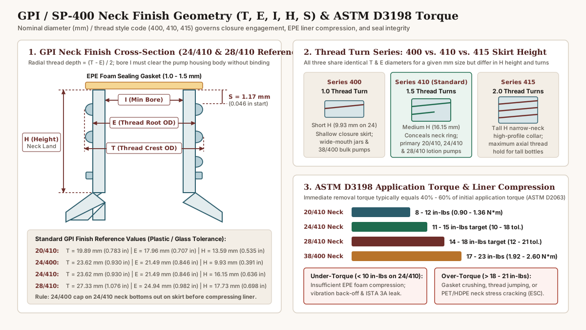
Decoding T, E, I, H, and S Dimensional Letters
Packaging engineers verify compatibility between a blow-molded PET or HDPE bottle neck and an injection-molded polypropylene (PP) pump collar using five standard GPI dimensional letters:
TDimension (Thread Crest Outer Diameter): The maximum outer diameter measured across the outside crests of the bottle neck threads. A nominal24 mmneck specifiesT = 23.62 mm(0.930 in), while a nominal28 mmneck specifiesT = 27.33 mm(1.076 in).EDimension (Thread Root Outer Diameter): The outer diameter of the cylindrical neck wall at the root between thread turns (E = 21.49 mm / 0.846 inon a24 mmneck;E = 24.94 mm / 0.982 inon a28 mmneck). Half of the difference betweenTandEdefines the radial thread engagement depth:Radial_Thread_Depth = (T - E) / 2 24/410 Radial Depth = (23.62 mm - 21.49 mm) / 2 = 1.065 mm (0.042 in) 28/410 Radial Depth = (27.33 mm - 24.94 mm) / 2 = 1.195 mm (0.047 in)IDimension (Minimum Inner Bore Diameter): The minimum clear internal diameter through the neck opening (18.49 mmon24/410;21.79 mmon28/410). Unlike simple screw caps, a lotion pump suspends a rigid cylindrical dosing housing (14.5 to 19.5 mmouter diameter) and a flared retention collar inside the bottle neck. If a heavy-walled glass or thick-parisonHDPEbottle narrowsIbelow the pump housing diameter, the cylinder binds against the interior neck wall and tilts the closure off axis.HDimension (Neck Finish Height): The vertical distance measured from the top flat sealing surface (finish land) down to the point where the neck transfer bead or lower support ring intersects the bottle shoulder.SDimension (Thread Start Distance): The vertical span from the top sealing surface to the start of the first thread pitch (~1.17 mm/0.046 in), which governs how far the closure rotates before engaging the upper thread flank.
Why Series 400, 410, and 415 Closures Are Not Interchangeable
While the first number sets diameter (20, 24, 28, or 38 mm), the second three-digit number dictates the number of continuous helical thread turns and the vertical neck height (H):
400Series (1.0Thread Turn, Shallow Skirt): Features a single360°continuous thread turn and a short vertical height (H = 9.93 mm / 0.391 inon24/400;H = 10.31 mm / 0.406 inon28/400). Because400closures have a shallow skirt, pairing a28/400pump with a tall cosmetic bottle neck leaves the lower transfer bead exposed. In personal care,400threads appear primarily on wide-mouth38/400backbar liter bottles (H = 10.97 mm / 0.432 in).410Series (1.5Thread Turns, Medium Flush Skirt): Extends neck height toH = 13.59 mm(0.535 in) on20/410,H = 16.15 mm(0.636 in) on24/410, andH = 17.73 mm(0.698 in) on28/410. The1.5continuous thread turns distribute axial clamping load across540°of thread contact while allowing the medium-height closure skirt to drop flush over the neck ring for a clean cylinder or Boston-round silhouette.415Series (2.0Thread Turns, Tall High-Profile Skirt): Extends neck height toH = 22.02 mm(0.867 in) on24/415andH = 24.56 mm(0.967 in) on28/415, providing two full rotations of thread engagement for slender, narrow-shouldered bottles that experience high lateral bending moments when the pump head is pressed.
GPI / SP-400 Finish |
Thread Turns & Skirt Profile | Crest OD T (mm / in) |
Root OD E (mm / in) |
Min Bore I (mm / in) |
Neck Height H (mm / in) |
ASTM D3198 Target Torque (in-lbs / N*m) |
Immediate Removal Torque (40% to 60%) |
|---|---|---|---|---|---|---|---|
20/410 |
1.5 turns, medium cosmetic skirt |
19.89 mm (0.783 in) |
17.96 mm (0.707 in) |
14.53 mm (0.572 in) |
13.59 mm (0.535 in) |
8 to 12 in-lbs (0.90 to 1.36 N*m) |
3.5 to 7.0 in-lbs (0.40 to 0.79 N*m) |
24/400 |
1.0 turn, shallow utility skirt |
23.62 mm (0.930 in) |
21.49 mm (0.846 in) |
18.49 mm (0.728 in) |
9.93 mm (0.391 in) |
10 to 14 in-lbs (1.13 to 1.58 N*m) |
4.0 to 8.4 in-lbs (0.45 to 0.95 N*m) |
24/410 |
1.5 turns, standard lotion skirt |
23.62 mm (0.930 in) |
21.49 mm (0.846 in) |
18.49 mm (0.728 in) |
16.15 mm (0.636 in) |
11 to 15 in-lbs (1.24 to 1.69 N*m) |
4.5 to 9.0 in-lbs (0.51 to 1.02 N*m) |
24/415 |
2.0 turns, tall narrow-neck skirt |
23.62 mm (0.930 in) |
21.49 mm (0.846 in) |
18.49 mm (0.728 in) |
22.02 mm (0.867 in) |
11 to 15 in-lbs (1.24 to 1.69 N*m) |
4.5 to 9.0 in-lbs (0.51 to 1.02 N*m) |
28/410 |
1.5 turns, heavy body-lotion skirt |
27.33 mm (1.076 in) |
24.94 mm (0.982 in) |
21.79 mm (0.858 in) |
17.73 mm (0.698 in) |
14 to 18 in-lbs (1.58 to 2.03 N*m) |
5.6 to 10.8 in-lbs (0.63 to 1.22 N*m) |
38/400 |
1.0 turn, wide backbar liter skirt |
37.49 mm (1.476 in) |
35.10 mm (1.382 in) |
31.93 mm (1.257 in) |
10.97 mm (0.432 in) |
17 to 23 in-lbs (1.92 to 2.60 N*m) |
6.8 to 13.8 in-lbs (0.77 to 1.56 N*m) |
Interchangeability Failure Mode: Thread styles 400, 410, and 415 are never interchangeable even when the diameter matches. Threading a 24/410 lotion pump (16.15 mm skirt depth) onto a 24/400 bottle neck (9.93 mm height) causes the bottom edge of the pump collar to strike the bottle shoulder 6.22 mm early, preventing the bottle’s top land surface from reaching the internal sealing gasket. Conversely, threading a 24/400 cap onto a 24/410 bottle neck leaves 6.22 mm of lower threads and the transfer bead exposed.
ASTM D3198 Application Torque, ASTM D2063 Retention, and Gasket Compression
A lotion pump closure seals against the bottle neck by compressing an annular expanded polyethylene (EPE) foam gasket (1.0 to 1.5 mm uncompressed thickness) or a molded low-density polyethylene (LDPE) plug seal against the bottle’s top land. Closure torque is calibrated and audited under two ASTM International standards and TricorBraun’s closure torque engineering guidelines:
ASTM D3198Application Torque Windows: Production capping chucks target11 to 15 in-lbs(1.24 to 1.69 N*m, with a broader plastic container tolerance of10 to 18 in-lbs) for a24/410lotion pump and14 to 18 in-lbs(1.58 to 2.03 N*m, tolerance12 to 21 in-lbs) for a28/410pump.ASTM D2063Torque Retention and Polymer Creep: Immediately after capping, removal (bridge) torque measures40% to 60%of the initial application torque (4.5 to 9.0 in-lbson24/410). Over the first24 hoursto28 daysof storage (ASTM D2063conditioning intervals), polypropylene closure threads undergo viscoelastic stress relaxation and theEPEfoam liner takes a15% to 25%compression set.- Under-Torquing vs. Over-Torquing Failure Thresholds: If initial application torque drops below
10 in-lbson a24/410neck (or if emulsion droplets contaminate the neck threads during filling and act as a slip lubricant),24-hourremoval torque falls below4 in-lbs, allowing closure back-off under parcel vibration. If application torque exceeds18 to 21 in-lbs, the polypropylene collar threads jump or strip across thePETneck crests, theEPEliner crushes unevenly around the pump flange, or rigidPETandHDPEnecks develop environmental stress cracking (ESC) when exposed to essential oils or surfactants.
Stroke Dosage (0.5 to 4.0 cc), Emulsion Viscosity (cP), and Filling Line Integration
Inside the pump housing, depressing the actuator drives a polyethylene piston down a precision-molded metering cylinder. The swept volume of that cylinder defines the pump’s stroke dosage in cubic centimeters (1.0 cc = 1.0 mL). Selecting the wrong chamber volume or fluid orifice diameter degrades both user ergonomics and line filling performance.
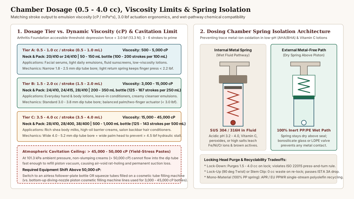
Dosage-to-Viscosity Calibration Matrix and <3.0 lbf Ergonomics
To satisfy the Arthritis Foundation Ease of Use threshold explored in our accessible pump handling guide, the vertical force required to depress the actuator head must remain below 3.0 lbf (13.3 N) across the entire stroke travel. Hydraulic resistance inside the pump stem scales directly with dynamic viscosity (cP or mPa*s, measured on a Brookfield rotational viscometer at 20°C to 25°C) and inversely with the fourth power of the stem and dip-tube bore diameter:
- Fine-Dosage Treatment Pumps (
0.5 to 1.0 ccper stroke |500 to 5,000 cP): Engineered for50 to 150 mLfacial moisturizers, lightweight serums, and fluid sunscreens on20/410or24/410necks. A100 mLbottle delivers100 to 200measured applications. Because the stroke travel is short (4.5 to 6.0 mm) and the return spring is light, one-finger or two-finger actuation stays at1.6 to 2.2 lbf. - Standard Daily Lotion Pumps (
1.5 to 2.0 ccper stroke |3,000 to 15,000 cP): The workhorse tier for200 to 350 mL(6.7 to 12 fl oz) hand creams, daily body lotions, and leave-in hair conditioners on24/410and28/410bottles (125 to 167strokes per250 mL). A3.0 to 3.8 mmdip tube bore paired with a contoured two-finger or palm saddle head keeps depression force between2.2 and 2.9 lbfafter3 to 6initial priming strokes purge air from the chamber. - High-Output Body & Backbar Pumps (
3.5 to 4.0 ccper stroke |15,000 to 45,000 cP): Built for500 to 1,000 mL(16.9 to 33.8 fl oz) rich shea body milks, high-viscosity barrier lotions, and salon conditioners on28/410or38/400necks (125 to 143strokes per500 mL). Moving4.0 mLof35,000 cPcream without pushing actuation force past4.5 to 6.0 lbfrequires a wide-bore cylinder, an oversized4.0 to 5.2 mm IDdip tube, and a broad palm-press actuator head (>= 28 to 35 mmsaddle width) with an extended nozzle reach so one hand can press while the other catches the ribbon of cream.
The 50,000 cP Atmospheric Cavitation Ceiling and Filling Machinery Selection
A dip-tube lotion pump does not “pull” liquid up from the bottle by mechanical traction; instead, as the internal return spring pushes the piston upward after a press, it creates a partial vacuum inside the metering chamber. Standard atmospheric pressure (101.3 kPa / 14.7 psi) acting on the free surface of the lotion inside the bottle forces the emulsion down and into the dip tube tip to refill the chamber.
- Why Dip-Tube Pumps Cavitate Above
45,000 to 50,000 cP: When a formulation exceeds45,000 to 50,000 cP(such as anhydrous body butters, heavy petrolatum barrier pastes, or creams with high Herschel-Bulkley yield stress), gravity and101.3 kPaatmospheric pressure cannot make the stiff paste slump laterally toward the dip tube intake fast enough to match the piston return rate. After5 to 10strokes, the dip tube cores a hollow air cavity (“rat-holing” or “tunneling”) at the bottom center of the bottle, draws air past the lower check ball, and permanently loses prime while40% to 70%of the cream remains stuck to the container walls. - Line Integration with a Piston
Cosmetic Filling Machine(3,000 to 45,000 cPBottles): For lotions within the3,000 to 45,000 cPpumpable window packaged in24/410or28/410rigid bottles, commercial packaging lines use a servo-driven volumetric piston cosmetic filling machine outfitted with bottom-up diving nozzles and positive pneumatic shut-off suck-back valves. During the fill cycle, the diving nozzle descends to5 mmabove the interior bottle floor and retracts upward at the exact rise velocity of the lotion meniscus. Bottom-up filling prevents two line defects that ruin lotion pump performance:- Aeration Pocket Elimination: Top-splashing a
25,000 cPemulsion traps macroscopic air pockets inside the bottle; when those air bubbles migrate into the dip tube intake, the consumer experiences sputtering strokes and mid-bottle prime failure. - Clean Neck Threads (
IandTZones): The positive suck-back valve snips viscous product strings cleanly as the nozzle clears the18.49 mm(24/410) neck bore, keeping emulsion off the upper sealing land and outer threads before the automatic dip-tube straightener funnel inserts the pump and the servo chuck capper tightens the collar to11 to 18 in-lbs.
- Aeration Pocket Elimination: Top-splashing a
- When to Switch to Airless Packs or a
Cosmetic Tube Filling Machine(>50,000 cP): Once formulation viscosity exceeds50,000 cP, packaging engineers eliminate the dip tube entirely via one of two equipment pathways:- Airless Follower-Plate Pump Bottles: Replace the dip tube with a rigid cylindrical container housing a precision-molded
LDPEmechanical follower piston (±0.03 to 0.08 mmradial interference fit) or collapsibleEVOHpouch at the base, as detailed in our airless pump bottle piston and vacuum dispensing specification. Each pump stroke creates suction that draws the entire bottom follower plate upward, scraping the interior cylinder walls clean (95% to 99%evacuation,<2% to 5%residual waste) up to80,000+ cP. - Squeeze Tubes on a
Cosmetic Tube Filling Machine: Transfer high-viscosity creams, ointments, and barrier pastes (50,000 to 150,000+ cP) into extruded polyethylene (PE), aluminum barrier laminate (ABL), or plastic barrier laminate (PBL) squeeze tubes paired with flip-top closures. On a rotary or inline cosmetic tube filling machine, bottom-up volumetric dosing nozzles inject the heavy paste from the closed shoulder upward toward the open tube tail, followed by optical eye-mark orientation, hot-air or ultrasonic tail sealing (PE/PBL), and date-code embossing.
- Airless Follower-Plate Pump Bottles: Replace the dip tube with a rigid cylindrical container housing a precision-molded
Internal vs. External Spring Pathways, Locking Heads, and Transit Testing
A standard lotion pump assembly contains 8 to 12 sub-components: actuator head, stem, closure collar, gasket liner, upper piston, housing cylinder, return spring, lower check-valve ball (or disk), and dip tube. How the return spring and check valve are arranged determines chemical stability and recyclability.
Spring Isolation: Wet SUS 316H vs. External Metal-Free vs. Mono-Material PP
| Pump Chamber Architecture | Spring & Check-Valve Materials in Fluid Path | Chemical Compatibility & Oxidation Profile | Mechanical Rebound & Viscosity Ceiling | Recycling Stream Classification (APR / EU PPWR) |
|---|---|---|---|---|
| Internal Metal Spring (Conventional Wet Path) | Coiled SUS 304 or molybdenum-bearing SUS 316H stainless steel spring + stainless or glass ball inside dosing chamber |
Vulnerable to low-pH acids (pH 3.2 to 4.0 AHAs/BHAs), L-ascorbic acid, benzoyl peroxide, and high chloride salts leaching Fe/Ni/Cr ions |
Crisp return up to 45,000 cP; high spring force available for 3.5 to 4.0 cc chambers |
Mixed-material assembly: Steel spring and glass ball require consumer pump removal prior to polyolefin bottle recycling |
| External Spring (Metal-Free Wet Pathway) | Return spring (SUS 304/316H) isolated in dry upper housing above piston seal; PP/PE chamber + borosilicate glass or LDPE/POM check valve |
100% metal-free fluid contact: Prevents rust-tinted initial strokes, metallic odor, and metal-ion-catalyzed browning of Vitamin C or retinol | Crisp mechanical return (0.5 to 2.0 cc standard); keeps wet path entirely inert polyolefin |
Mixed-material assembly (contains isolated metal spring), though available with shatterproof polymer valves |
All-Plastic Mono-Material (100% PP / PE) |
Injection-molded polypropylene helical spring, polymeric bellows, or dome elastomer return + molded PP/PE valve |
100% metal-free and glass-free: Inert across acidic, alkaline, and salt-heavy personal care emulsions | Best suited to 500 to 25,000 cP (1.0 to 2.0 cc); slightly slower rebound in cold shower environments |
Full mono-material pass: Entire bottle + pump enters single-stream polyolefin (PP/PE) recycling without disassembly |
In an internal-spring pump, lotion drawn into the dosing chamber after the first prime sits in continuous contact with the coiled stainless steel spring between uses. While standard SUS 304 (18% Cr, 8% Ni) resists neutral oil-in-water body lotions (pH 5.5 to 7.0), body treatments formulated with glycolic, lactic, or salicylic acid (pH 3.2 to 4.0), L-ascorbic acid, peroxides, or high quaternary ammonium / chloride salt loads gradually pit the passive oxide film on 304 steel (and can even attack SUS 316H during 40°C accelerated stability aging). Trace iron, nickel, or chromium ions leach into the 1.5 to 2.0 cc chamber volume, turning the first stroke expelled after a weekend brown or orange and accelerating free-radical oxidation of active ingredients. Specifying an external-spring metal-free pathway, such as the architecture documented in Aptar Beauty’s GSA metal-free pathway dispensing pump, positions the steel spring above the upper piston seal so the emulsion contacts only virgin polypropylene (PP) and polyethylene (PE).
Locking Mechanisms (Lock-Down vs. Lock-Up vs. Clip) and ISTA 3A Validation
As highlighted in our accessible pump ergonomics note, ISO 22015:2019 advises against packaging closures that require simultaneous press-and-rotate hand actions unless mandated for child safety, and asks that reclosing actions minimize splashing and product waste. The three commercial pump locking styles behave very differently in daily use and parcel shipping:
- Lock-Down (
Push-and-Turn): Ships from the pump factory with the actuator depressed and twisted into internal collar threads. While compact during bulk pallet shipping, re-locking a primedlock-downbottle for travel requires depressing the head to the bottom of its stroke and twisting clockwise, which purges1.5 to 4.0 ccof lotion out of the nozzle onto the user’s hand and violatesISO 22015:2019single-action guidance. - Lock-Up (
90° Quarter-Turn Twist-to-Lock): Locks and unlocks in the elevated (up) position by rotating the actuator head90°so vertical guide ribs on the stem move into or out of alignment with internal collar slots. Because the stem never travels downward to lock, re-locking discharges0 ccof product, requires only a low-torque horizontal twist, and leaves the internal return spring uncompressed during warehouse storage. - Removable Stem Clip (
C-Collar Clip): Snaps a rigid polypropyleneC-cliparound the exposed stem between the underside of the actuator head and the top of the closure collar. It provides visual tamper evidence,0 ccpurge waste, and reusable travel immobilization inside gym bags.
For e-commerce and parcel distribution, filled lotion pump bottles are validated against ISTA 3A parcel delivery simulation (atmospheric conditioning, random over-the-road vibration with top-load pressure, and multi-orientation free-fall drops for packages up to 70 kg / 150 lb) and ASTM D4991 / filled-container vacuum leak testing (-68 to -95 kPa / -20 to -27 inHg differential pressure simulating unpressurized air cargo hold altitudes). Passing ISTA 3A without a secondary induction seal requires 11 to 18 in-lbs of retained cap torque, a lock-up or clip-locked stem that cannot depress under top-load vibration, and an upper piston lip seal that resists -95 kPa vacuum pull.
Dip Tube FBOG (“From Bottom of Gasket”) Sizing and Tip Cut Geometry
The most frequent dimensional error when pairing a stock lotion pump with a new bottle mold is specifying the dip tube by measuring only the visible plastic tubing protruding below the pump housing. Packaging manufacturers specify dip tube length exclusively by FBOG (“From Bottom of Gasket”).
The FBOG Linear Measurement Standard and Worked Calculation
As defined in O.Berk Company’s FBOG dip tube engineering specification, FBOG is the total linear distance measured from the underside (bottle-sealing face) of the closure’s EPE/PE gasket inside the cap down to the distal tip of the dip tube. Measuring from the bottom of the gasket eliminates supplier-to-supplier variations in pump housing sub-assembly depth (22 to 38 mm depending on chamber cc volume) because the underside of the gasket rests directly against the bottle’s top sealing surface (finish land).
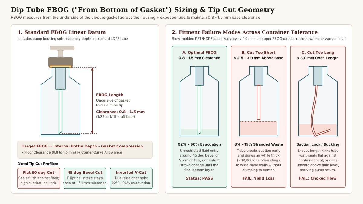
To calculate the target FBOG for a straight vertical center-dip configuration, apply the following dimensional formula:
Target_FBOG (mm) = D_internal_bottle_depth - C_gasket_compression - G_floor_clearanceWhere:
D_internal_bottle_depth: Vertical depth inside the bottle measured with a depth micrometer from the top flat sealing surface (finish land) straight down to the interior container floor directly beneath the neck center (mm).C_gasket_compression: Axial compression of theEPEfoam liner when tightened toASTM D3198specification (11 to 18 in-lbs), typically0.3 to 0.5 mm(25% to 35%of a1.2 mmliner).G_floor_clearance: Target vertical gap between the distal dip tube tip and the interior bottle floor, specified at0.8 to 1.5 mm(~1/32 to 1/16 in) to accommodate±1.0 mmblow-molding base thickness tolerance (push-uporpuntvariation).
Worked Engineering Calculation (250 mL Cylinder Bottle with 24/410 Neck and 2.0 cc Pump):
Suppose a 250 mL PET bottle has an overall external height of 148.0 mm, a center base push-up (punt) wall thickness of 3.2 mm (D_internal_bottle_depth = 148.0 - 3.2 = 144.8 mm), an EPE gasket compression offset of C_gasket_compression = 0.4 mm at 13 in-lbs torque, and a target bottom clearance of G_floor_clearance = 1.2 mm:
Target_FBOG = 144.8 mm - 0.4 mm - 1.2 mm = 143.2 mm (specify as 143.0 mm +/- 0.5 mm)(Note: If a low-viscosity lotion <5,000 cP uses a deliberately curved dip tube designed to sweep into the outer chime corner when the nozzle faces forward, engineers add a +3.0 to +6.0 mm curvature allowance beyond D_internal_bottle_depth and orient the tube bend parallel to the actuator nozzle).
Bottom Clearance Failure Modes and Distal Tip Cut Profiles (Flat 90° vs. 45° Bevel vs. V-Cut)
Even when nominal FBOG is calculated accurately, extradition blow-molded (EBM) HDPE bottles and injection-stretch blow-molded (ISBM) PET bottles exhibit ±0.8 to ±1.2 mm vertical variation in interior floor height across mold cavities. Pairing the 0.8 to 1.5 mm clearance window with the correct distal tip cut prevents both premature air draw and bottom suction lock:
| Fitment / Tip Cut Configuration | Bottom Clearance / Contact Geometry | Evacuation Yield (% of Net Fill Dispensed) |
Hydraulic Behavior & Dominant Failure Mode |
|---|---|---|---|
Optimal FBOG + 45° Bevel Cut |
0.8 to 1.5 mm above interior floor; diagonal elliptical orifice (45° slice) |
92% to 95% evacuation in 3,000 to 25,000 cP lotions |
Standard Pass: Even if a thick-bottomed bottle (+1.0 mm base tolerance) touches the lowest point of the bevel tip, the angled upper half of the elliptical opening remains unobstructed for fluid intake. |
Optimal FBOG + Inverted V-Cut (Notched Tip) |
0.0 to 1.0 mm (can rest lightly on floor); dual opposing V-notches cut into tube end |
93% to 96% evacuation in 15,000 to 45,000 cP rich creams |
High-Viscosity Pass: Preferred for stiff, wide-bore (3.8 to 5.2 mm ID) dip tubes on 2.0 to 4.0 cc pumps. Dual side notches prevent floor sealing while drawing the final 1.5 mm film of cream off the base. |
Defect 1: Tube Cut Too Short (>2.5 to 3.0 mm Clearance) |
Distal tip hangs >2.5 to 5.0 mm above the container floor |
85% to 90% evacuation (8% to 15% stranded waste) |
Premature Air Draw: Once the lotion level drops to the suspended tube tip, the pump sucks air and loses prime. Wide-base bottles chosen for anti-tip stability strand the highest volume (20 to 38 mL wasted in a 250 mL pack). |
Defect 2: Tube Cut Too Long (>3.0 mm Over-Length) |
FBOG exceeds internal bottle depth by >3.0 mm without controlled corner sweep |
Erratic / Choked Flow (Up to 25%+ stranded if kinked) |
Buckling or Suction Lock: A stiff tube forced against the bottom punt either kinks sharply at mid-height (choking the bore), curls upward so the tip points above the bottom lotion layer, or presses a flat 90° cut flush against the floor like a vacuum suction cup (>5.0 lbf press stall). |
Specification Verification Checklist for Packaging and QA Teams
Before releasing a lotion pump bottle specification for production tooling or incoming quality inspection (AQL sampling), verify all six mechanical checkpoints together with the external one-hand ergonomics criteria:
- Confirm Full
GPIFinish Match (Diameter+Series): Verify that both the bottle neck drawing and the pump closure drawing specify the identicalGPI / SP-400code (20/410,24/410, or28/410), and check that the bottle’s minimum inner bore (I) provides at least0.8 to 1.2 mmof radial clearance around the pump housing cylinder. - Audit Application and
24-HourRemoval Torque (ASTM D3198/D2063): Calibrate capping chucks to11 to 15 in-lbs(24/410) or14 to 18 in-lbs(28/410) on clean, dry threads, and verify24-hourremoval torque stays within40% to 60%of application torque (>= 5.0 in-lbsminimum retention). - Match Chamber Dosage (
cc) and Bore (ID) to Brookfield Viscosity (cP): Pair0.5 to 1.0 ccpumps with500 to 5,000 cPfluids,1.5 to 2.0 ccpumps with3,000 to 15,000 cPlotions, and3.5 to 4.0 ccwide-bore pumps with15,000 to 45,000 cPcreams; confirm full-stroke palm depression force stays below3.0 lbf(13.3 N) after3 to 6priming strokes. - Enforce the
50,000 cPCavitation Gate: Do not put non-slumping creams or pastes above45,000 to 50,000 cPinto an atmospheric dip-tube bottle; route3,000 to 45,000 cPbottles to a bottom-up diving-nozzle piston cosmetic filling machine, and route>50,000 cPpastes to airless follower-plate bottles or squeeze tubes on a cosmetic tube filling machine. - Select Wet-Pathway Spring Isolation & Zero-Purge Locking: Specify an external-spring metal-free pathway (or
100% PPmono-material pump) for any formula belowpH 4.5or containing Vitamin C, retinoids, peroxides, or high electrolytes; specify a90°lock-upactuator or removable stemC-clip(0 ccre-lock purge) validated toISTA 3Aand-95 kPavacuum leak standards. - Specify Dip Tube by
FBOGwith a45° BevelorV-CutTip: Measure internal bottle depth from the top sealing land to the floor across min/max mold cavities, subtract0.3 to 0.5 mmgasket compression and0.8 to 1.5 mmbottom clearance, and specify a45°bevel or invertedV-cutdistal tip to guarantee92% to 96%product evacuation.